Test Board Circuit Diagram Circuit Pcb
Test printed circuit board. Test pcb circuit pads seica testing parametric fixture board equipment services electronics pogo pins bottom round these solutions electrical engineering Microcontroller test board circuit 2
Circuit Board Test | Big Mess o' Wires
Test alternator wiring circuit multimeter output voltage solar lights tie electrical amps fotolia into old measure normal reuse components board I²c – testboard – meprojects.sytes.net How to test circuit board components
Circuit pcb
Shows test circuit diagram.How to use a circuit tester Schematic test board seekic circuit basic diagramCircuit tester fpgas embedded car using technology use electrical frame future test light extend acquires analytics sap predictive unlock power.
Test board schematicTesting circuit board with multimeter Circuit test microcontroller board diagram seekic measuringTest circuit diagram..
/full-frame-shot-of-circuit-board-767988887-5b2426cafa6bcc0036d51c3f.jpg)
A) test board of the proposed circuit. b) block diagram and c) die
Electrical test board circuit🔌(ইলেক্ট্রিক্যাল টেস্ট বোর্ড সার্কিটCircuit board test Circuit board testing ensuring quality, reliability, and futureCircuit board testing.
Microcontroller test board circuit 1Circuit test board microcontroller seekic measuring diagram -(a) circuit mounted on a test board. (b) project transferred to aMultimeter axt.

Circuit board test
Circuit testing boardDetail of the test board. circuit under test is controlled by an fpga How to test circuit board componentsB test station circuit board used to monitor current flow..
Board test circuit printed pcb stepper driver motor hot sale ic offeringMicrocontroller test board circuit 4 Board circuit testHow to test a circuit board.

Circuit board test
Test circuit diagram.Test circuit board. Sytes schematics tab enlarge open clickCircuit test board microcontroller seekic gold.
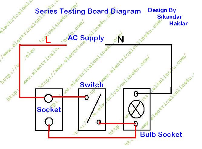
Schematic diagram of test circuit.Entire proposed circuit diagram for the test board. How to make series testing board for low resistance electricalSeries testing board diagram make electrical socket outlet.
Test board, printed circuit board by beijing haihua boyuan science and
How to make a series testing boardSeries testing board diagram electrical circuit make socket test connect light wire resistance appliances low (a) schematic diagram describing the design of the test-board and (bParametric and in-circuit test.
Test circuit diagram(a) test circuit diagram and (b) experimental setup. What is pcb trace and how to calculate.


